So I started to get all necessary parts in order to build my own version. You can see this post as documentation of my own journey as well as instruction.
Parts:
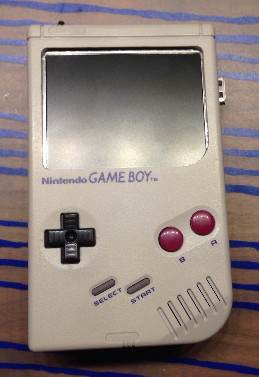
- Gameboy case (classic model DMG-01) with it's internals
- 3.5" TFT display
- Raspberry Pi Model B+
- Audio amplifier PCB - mine was left over and a bit different
- Common Ground PCB
- Two push-buttons and one mini push button
- USB Female Type A SMD Connector
- Prototype board (flexible solderable board)
- Wires, wires, wires
- An empty Gameboy game cartridge
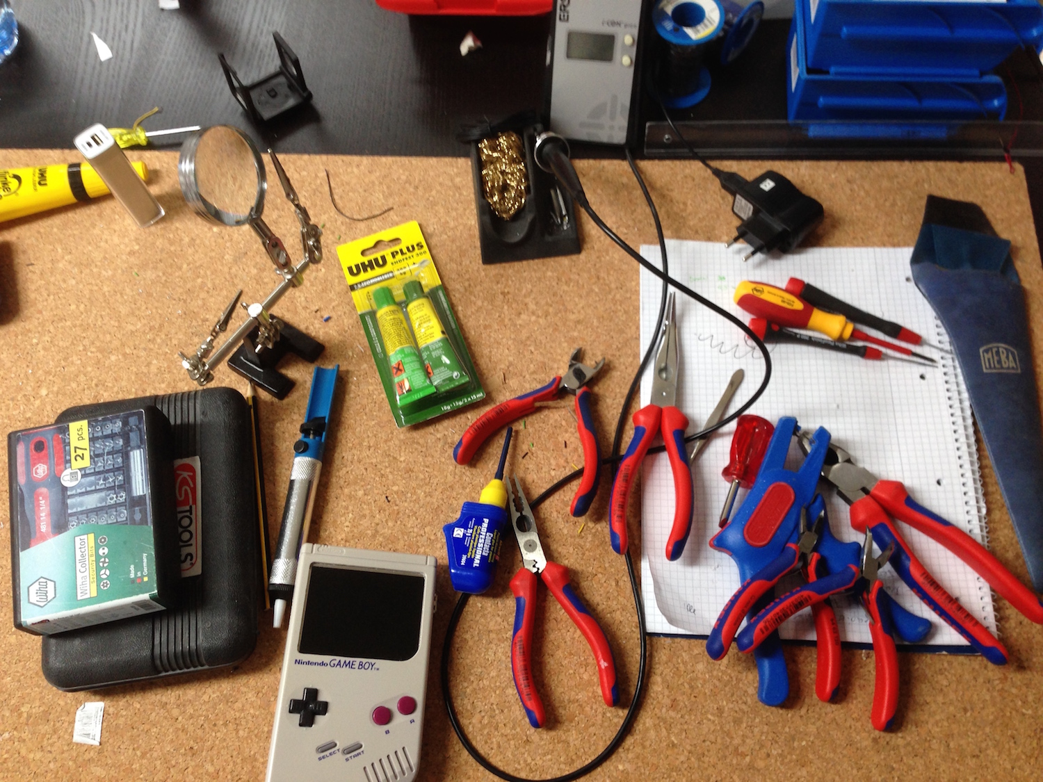
Tools:
- Soldering iron (the best is a thermal controlled with midi and fine tips)
- Triwing screwdriver to open the Gameboy case
- Screwdrivers
- Pliers
- Side cutter
- Dremel
- Drill
- Glue (2K Epoxy, I used UHU Endfest 300)
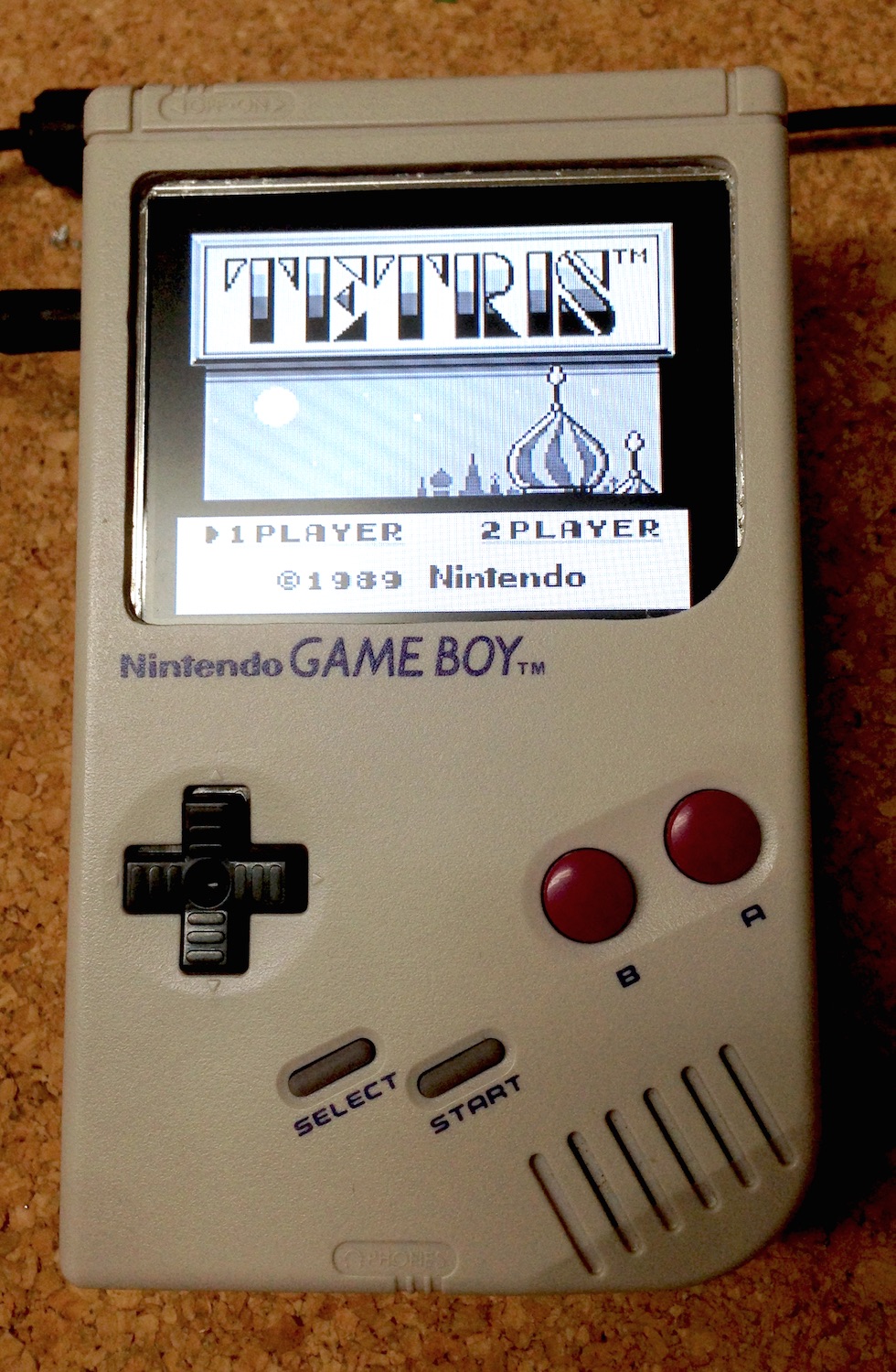
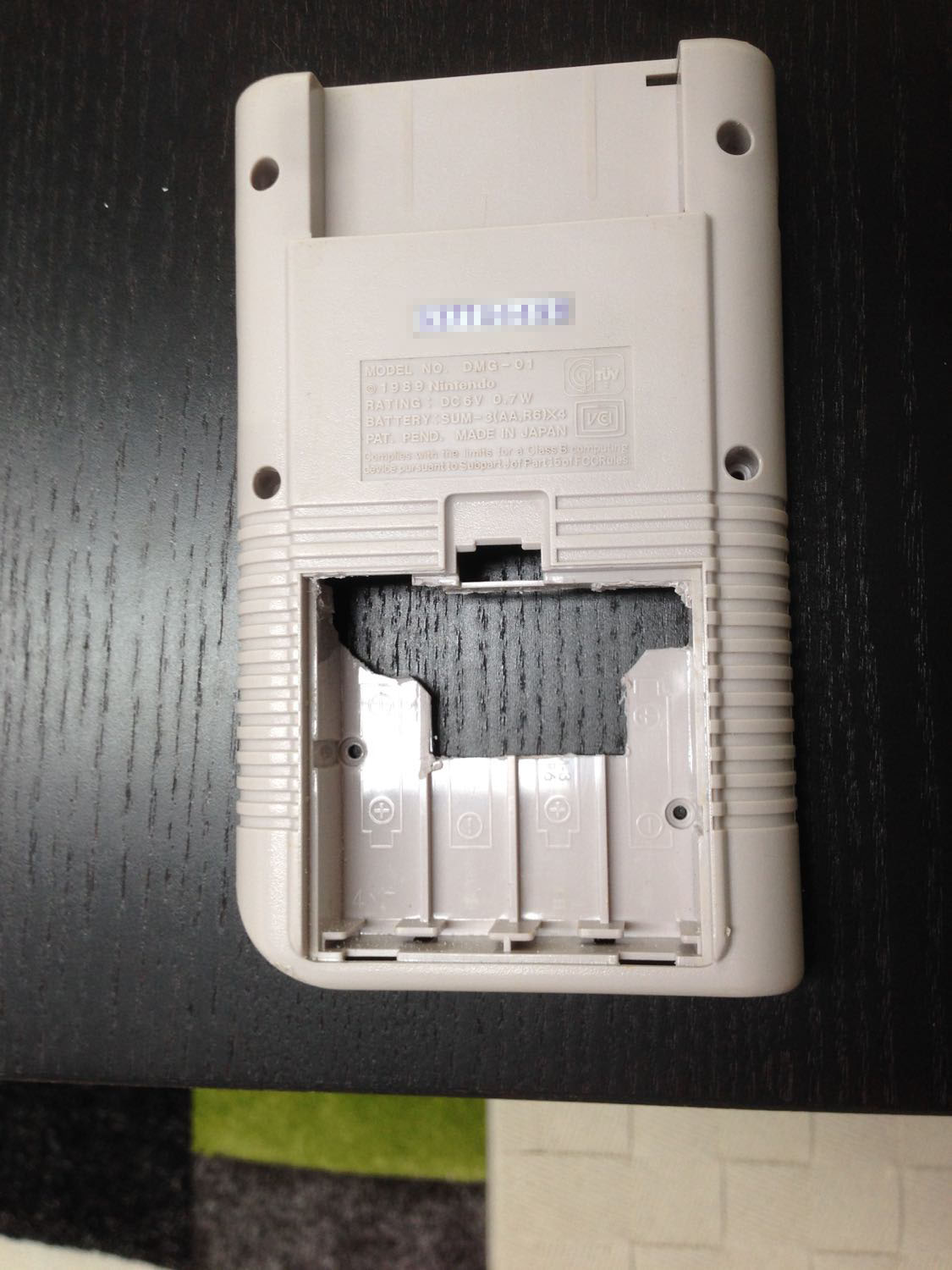
At first I searched eBay for used Gameboys. There are plenty of sellers on Amazon and eBay. Most of them sell complete sets with tons of cartridges. There are some cheap offers with broken Gameboys. I decided to take one which is not too yellow ([How to make them nice and shiny again]). The case should not be damaged, the buttons and their pads should work. Gameboys with broken controls are worthless.
The second thing was the display. The original Gameboy display has a size of 2,66" (which is about 66 millimeters). The maximal display size which fits into the case is about 3.5" (about 89 millimeters) in diagonal. A 3.5" display will leave some 5 millimeters space in the case. Larger displays won't fit. So anything that is 3.5" should fit. The connection to the display is FBAS/Composite - one of the cons. There is always some noise because the signals are analog and not digital. The picture gets fuzzy especially at the borders. Raspberries have a DSI display connector but it was quite complicated for me to find a DSI display. In the end it seemed to me that you need the display and a driver PCB which controls the display. I could also not find a 3.5" display that accepts HDMI or DVI/DisplayPort. This would have been the better solution.
Next was the Raspberry Pi itself. Lucky me: At that time Raspberry Pi B+ model was released. Model B+ has more USB, more GPIO and improved audio. On the other side, FBAS/Composite was merged in the audio port. But well, that's not a problem. Model B would be sufficient but B+ is much more handy and fits like a glove. The SD-Card is a Micro-SD in Model B+. This needs much less space.
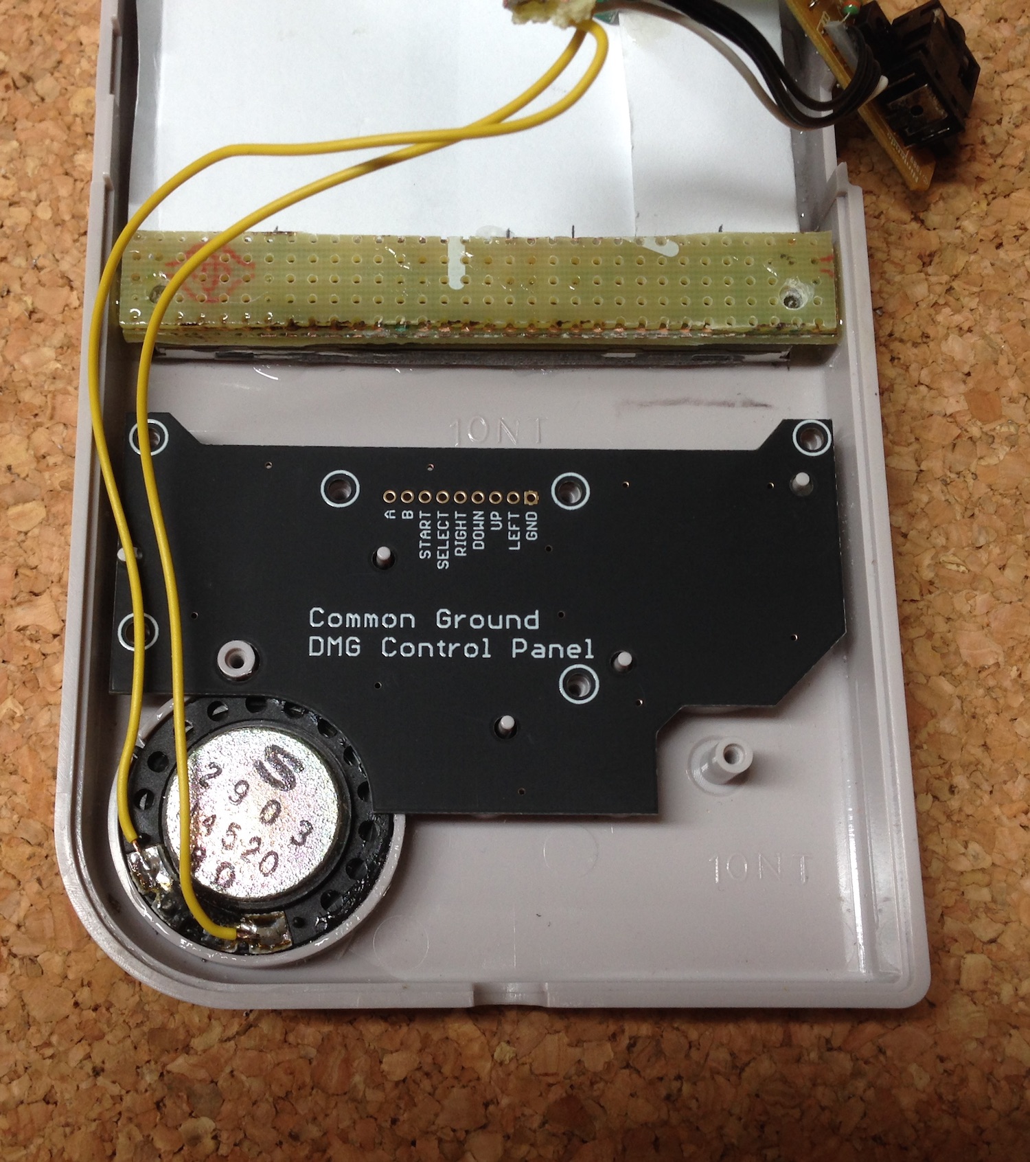
Only few components more were needed: The Common Ground DMG PCB (for connecting the controller/buttons), an audio amplifier (I had one already from previous projects) and some additional buttons. In order to run the Gameboy I used a switching power supply. The Common Ground DMG PCB took the most time for shipping (I ordered it from Germany in the USA). I had also some smaller stuff which I used to assemble the RaspiBoy.
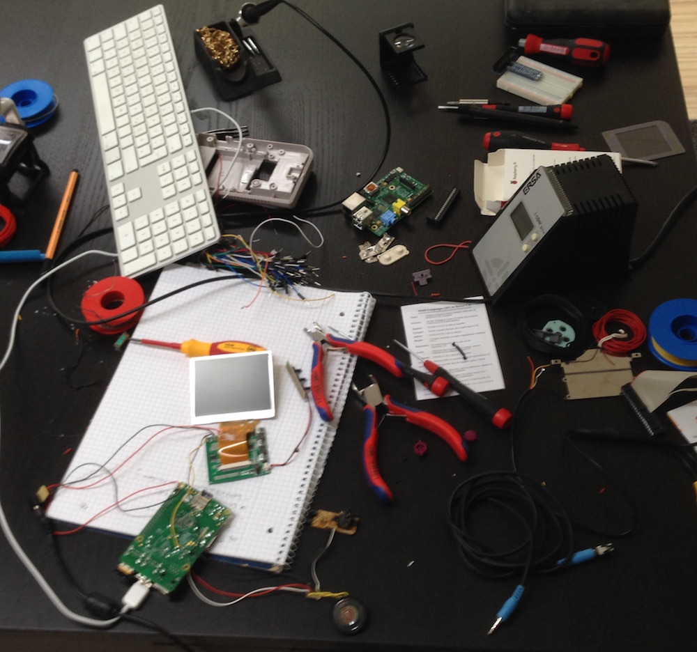
The order of steps is not the one I used. I tried to solder all the components at first together to see whether they work together (audio, video). After that I started to work on the case. This order is much faster and efficient than I did it in the first place.
Preparation
Gameboy case
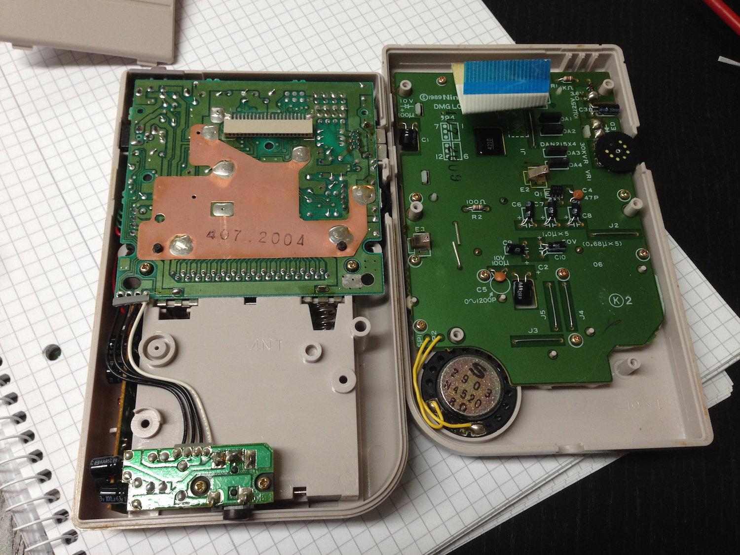
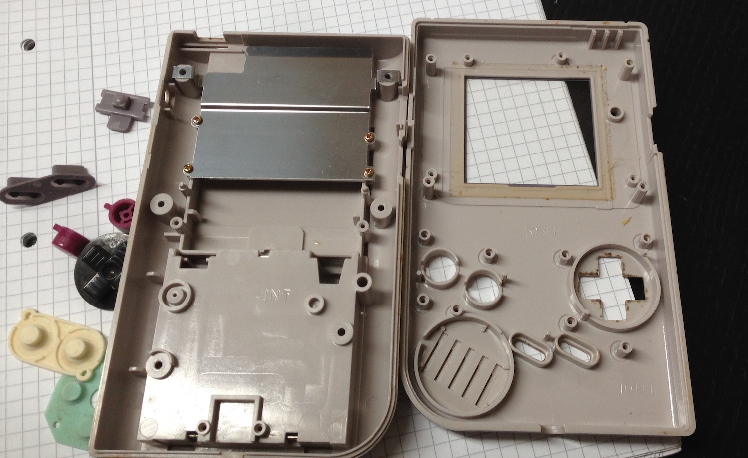
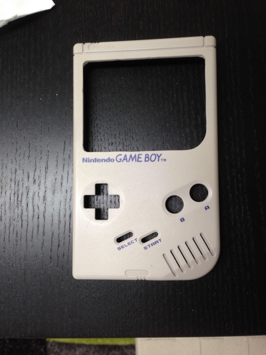
Open the Gameboy case and unscrew everything in the case. I reused parts of the Gameboy like the audio adapter, the power connector and the speaker and some screws. So don't throw away the inner Gameboy stuff! Peel of the display cover, put all buttons and the button pads aside. Remove the battery connectors from the case - you won't need them anymore. Afterwards clean the case (front, back and the battery cover). Clean the buttons and the pads, if necessary. Clean the cover if necessary (I used a pressure washer to speed it up).

Recycle Gameboy parts
Don't throw away the inner Gameboy stuff! Rather desolder the power connector (it's a connector with 3mm outer and 1,2mm inner diameter), speaker and the audio connector PCB. Leave the four wires on the PCB, detach the whole unit from the main PCB. Keep the buttons and the pads for later.
The Display
My display is a newer generation (in comparison to the other versions when you google for TaoTronics 3.5). It has a detached control button bar which results in a smaller driver board. And, that's perhaps the most important part, the inner voltage is 3.3V and not 5V. This means you can power the Raspberry Pi and the display without any voltage converter or further hacks. You'll need about
Great work until here.
Case works
Cutting the case
Have an idea first how it should look like or look at the pictures before cutting! Make sure you don't cut stuff you would need later on.
In order to fit everything within the case you'll need additional space. This can be done mainly by removing parts of the case.
Caution: cut off is cut off and mistakes on the cases' outside can't be unseen anymore. Practice around a bit before really cutting. I ripped myself some scattered lines in the case while enlarging the display corners. I could heal some of the wounds by applying sand paper, still the irregularities are there.
Take carefully a Dremel and cut with caution on 5-10 kRPM. The plastic (it's ABS) will start to melt as soon as you stay too long in one place or press too firm. The frazzle along your cutting line is not a problem, you can cut it off with a knife later on.
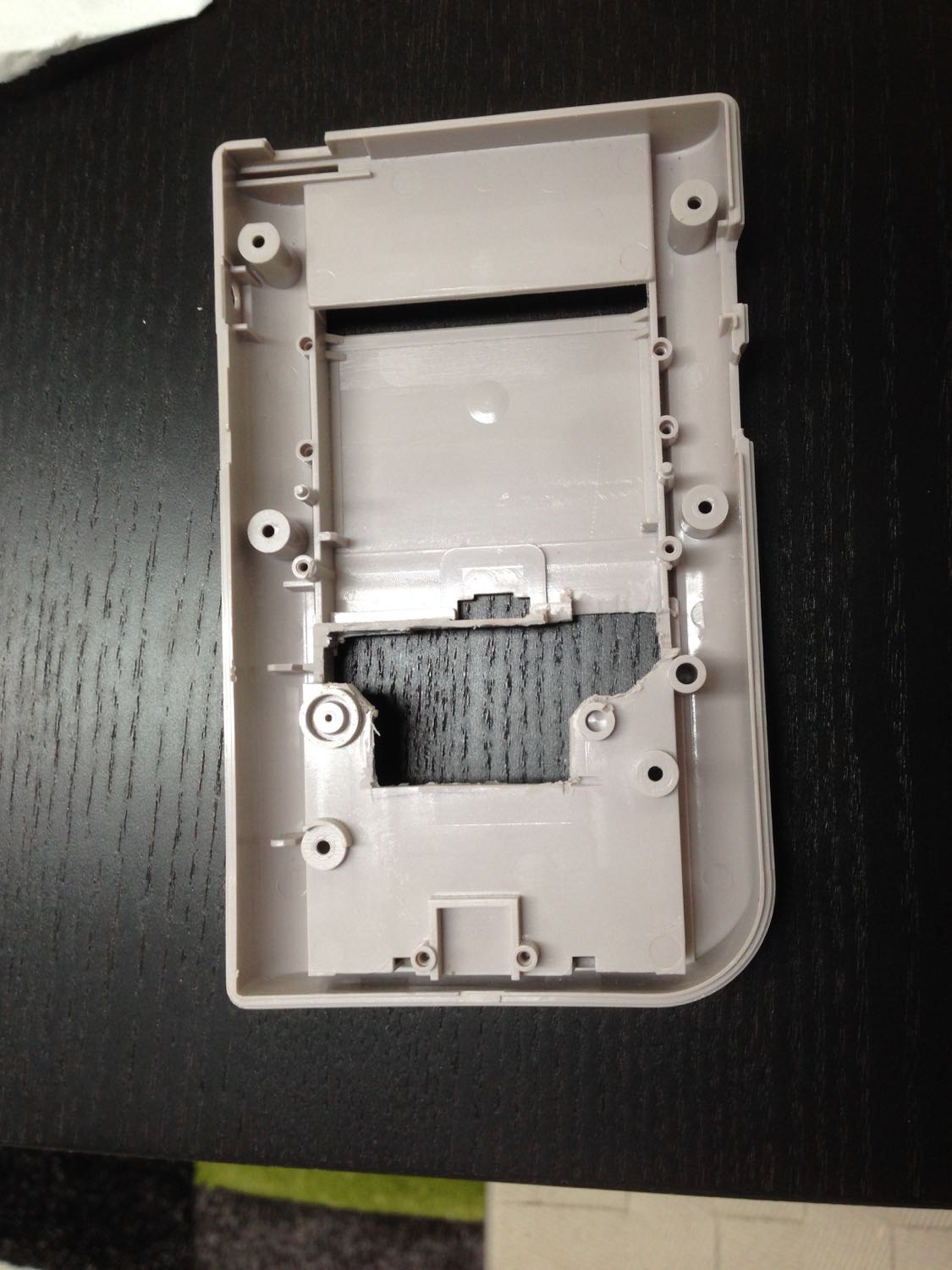
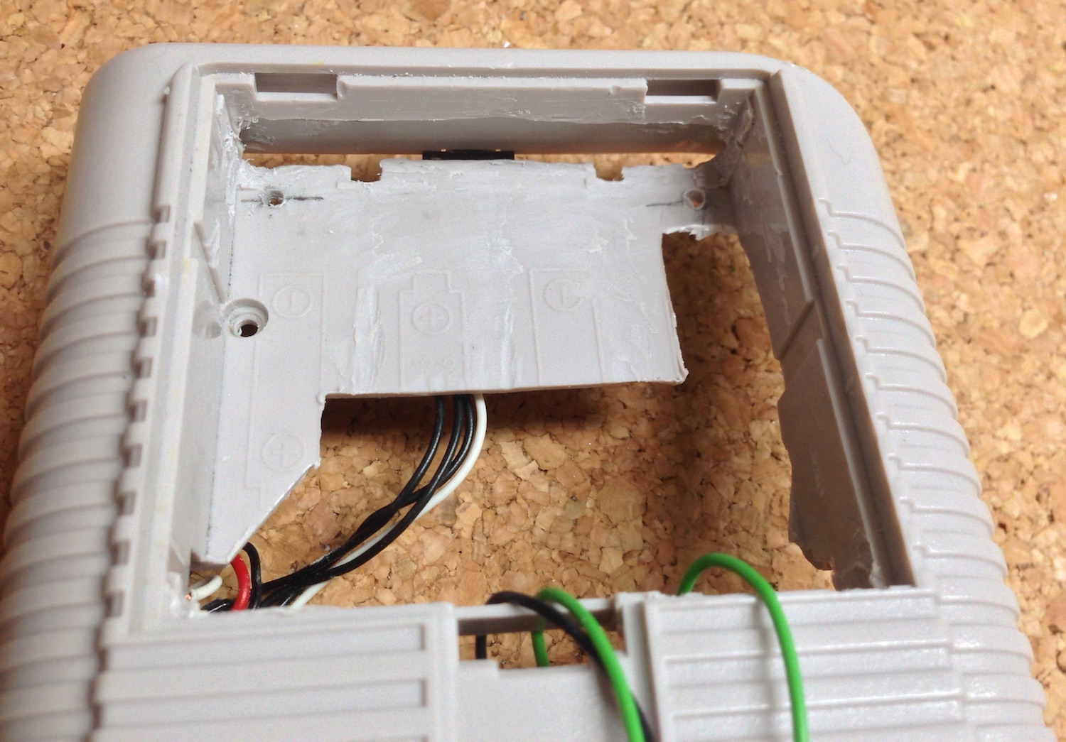
First cut off the screw towers on the front panel of the case where the display way mounted. You will have to cut the room for the display next. Cut along the line where the display cover was placed. This way you have a predefined contour. Next is the rear cover. You will need the space of the battery enclosing to put the Raspberry in. Cut the enclosing from the top and the front, where the battery cover snaps in. Keep some of the enclosing. This way you can reuse the battery cover. And don't remove all of the enclosing. You'll also need the base where the audio jack is mounted. Keep in mind, that the GPIO pins are higher than the rest, so you'll probably remove on the pin side some more. In my first approach, I left too much plastic. The GPIO pinstripe was laying on the plastic and the whole Raspberry was crooked. Make sure, that you remove the embossed battery separators. On the pictures above they are still there, They just steal space. When fitting the Raspberry you'll discover some potential to remove some more of the cover plastics. It allows you to have a better placing for the Raspberry.
After removing a strip for GPIO, the battery separator embossing and a slot for the Raspberry's SD card end.
Mount the display
The display opening is now wide enough now to take a 3.5" display. Place your display over the hole and rotate it by 180° so the connector cable faces towards the top of the case. It improves the space utilization. You can later rotate the picture of the display using the settings buttons. Fix it using the glue and give it a day to harden.
Lessons learned: My display sliped a bit. Next time I'll fix it while the glue is about to dry.
Now most of the screw towers are gone or covered by something. You definitively don't want to glue the case (else you won't ever open it). Using wire straps for holding the parts together was not an option for me.
My solution: Create own attachments.
I took a soldering board (can be also anything else which is quite stable). I measured the width of the inner of the case and cut one piece (some 10mm x 85mm) and two smaller pieces (10mm x 10mm). It must touch the inner case and must not have more than 1mm space left. I placed the smaller plates above the outer edges and glued both together. Then I placed the glued parts over the lower part of the display and adjusted the position using the back cover. The back cover has 6 holes for screws: 2 at the top, 2 at the middle and 2 in the battery enclosure. I used the middle holes and made sure the attachment bar is positioned right in the center of the screw holes. Then I marked the position in the case and the position of the screw holes. Find some screws that would fit (you have some spare screws from the case) and drill tiny holes that are a bit smaller than the screws. Fit the screws to the case depth: The original screws are now too long because the display needs some space. Therefore you've got to shorten them a bit. I did that using a grinding wheel. You can use your Dremel for that too. Now you need to fix the attachment bar precisely above the display. Mix the glue (mine sticks up to 300kN/cm2, it's very solid) and glue it to the inner case. This way you have the first attachment to screw the two cover parts together.
Later on I discovered I would need another attachment. This is to close the case in the upper part. Attaching and holding the attachment while the glue hardens was a bit tricky since the attachment wants to slide down. That was my solution.
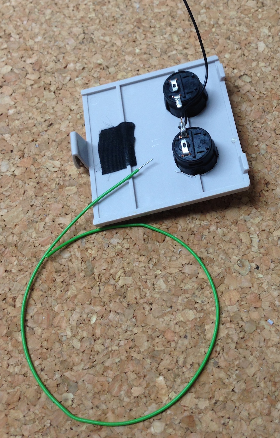
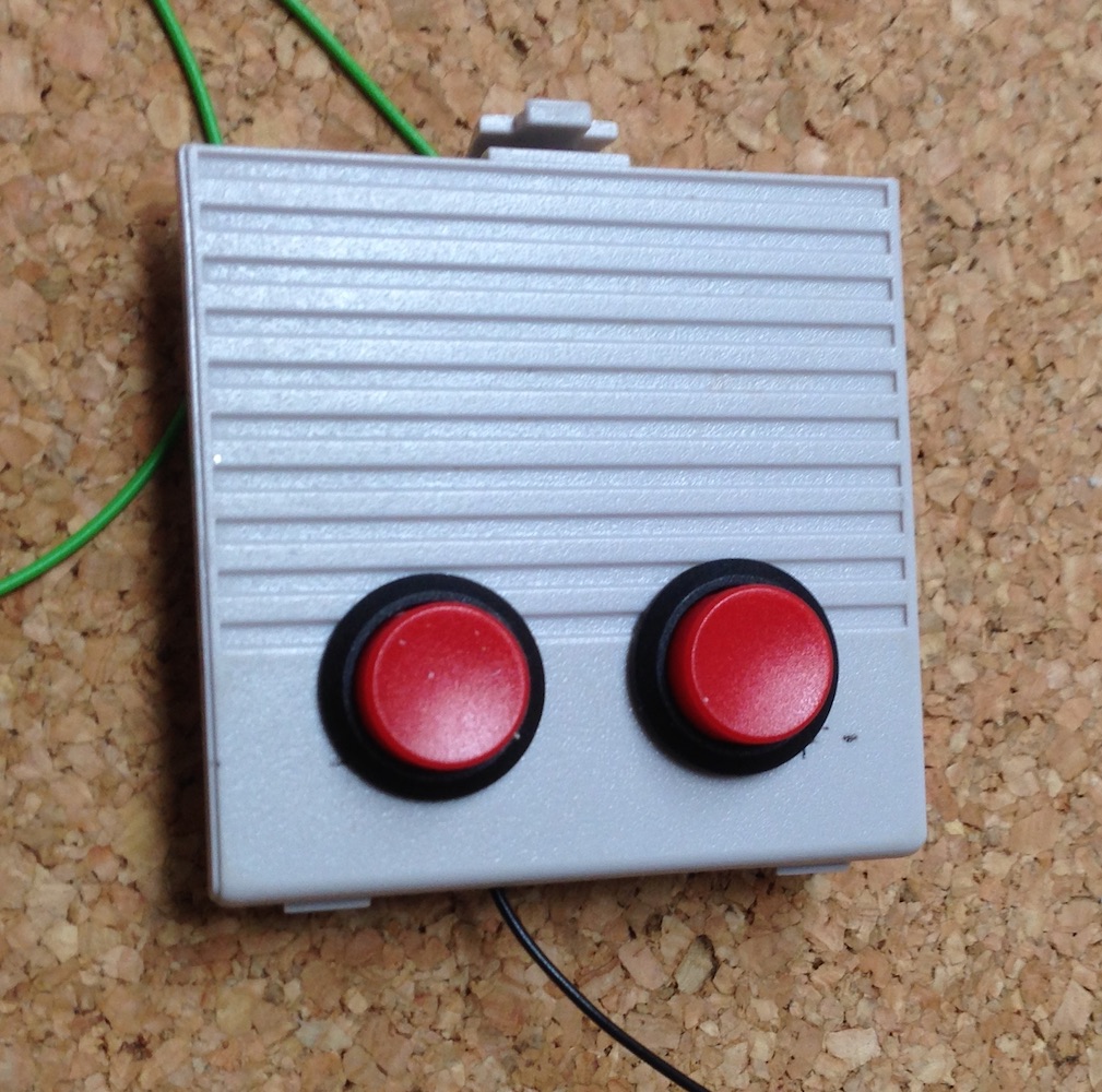
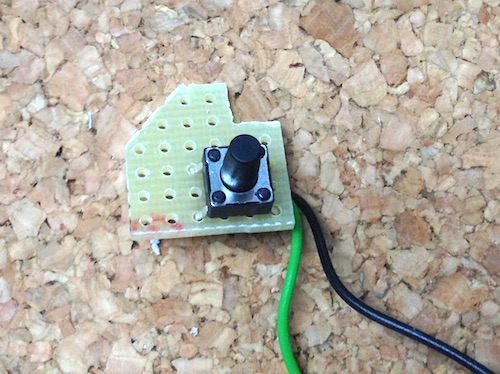
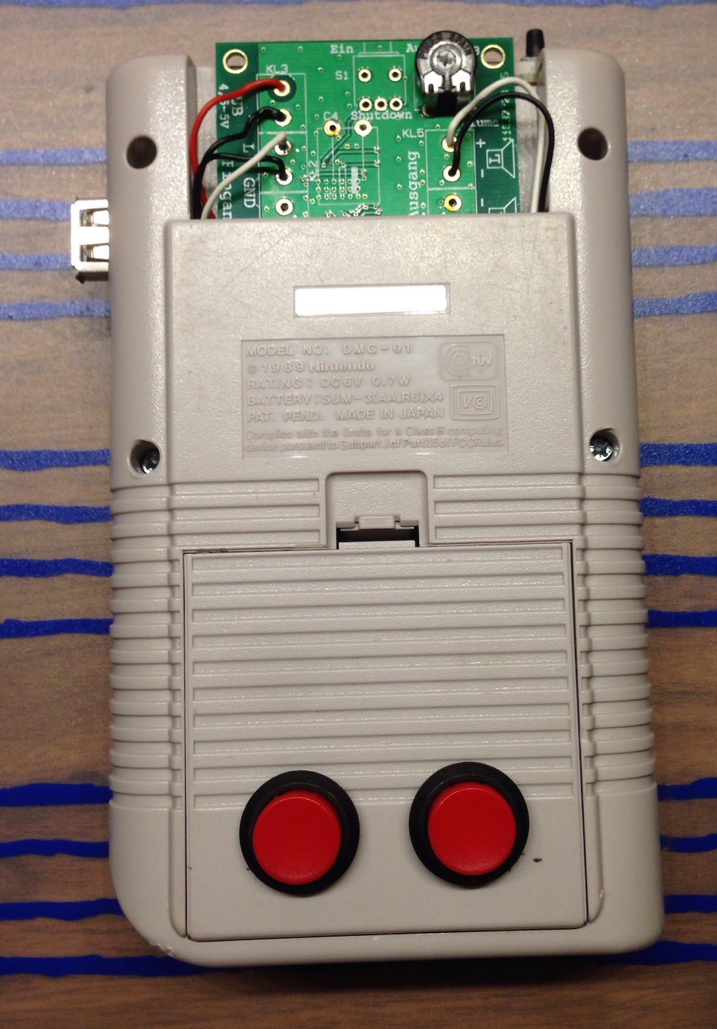
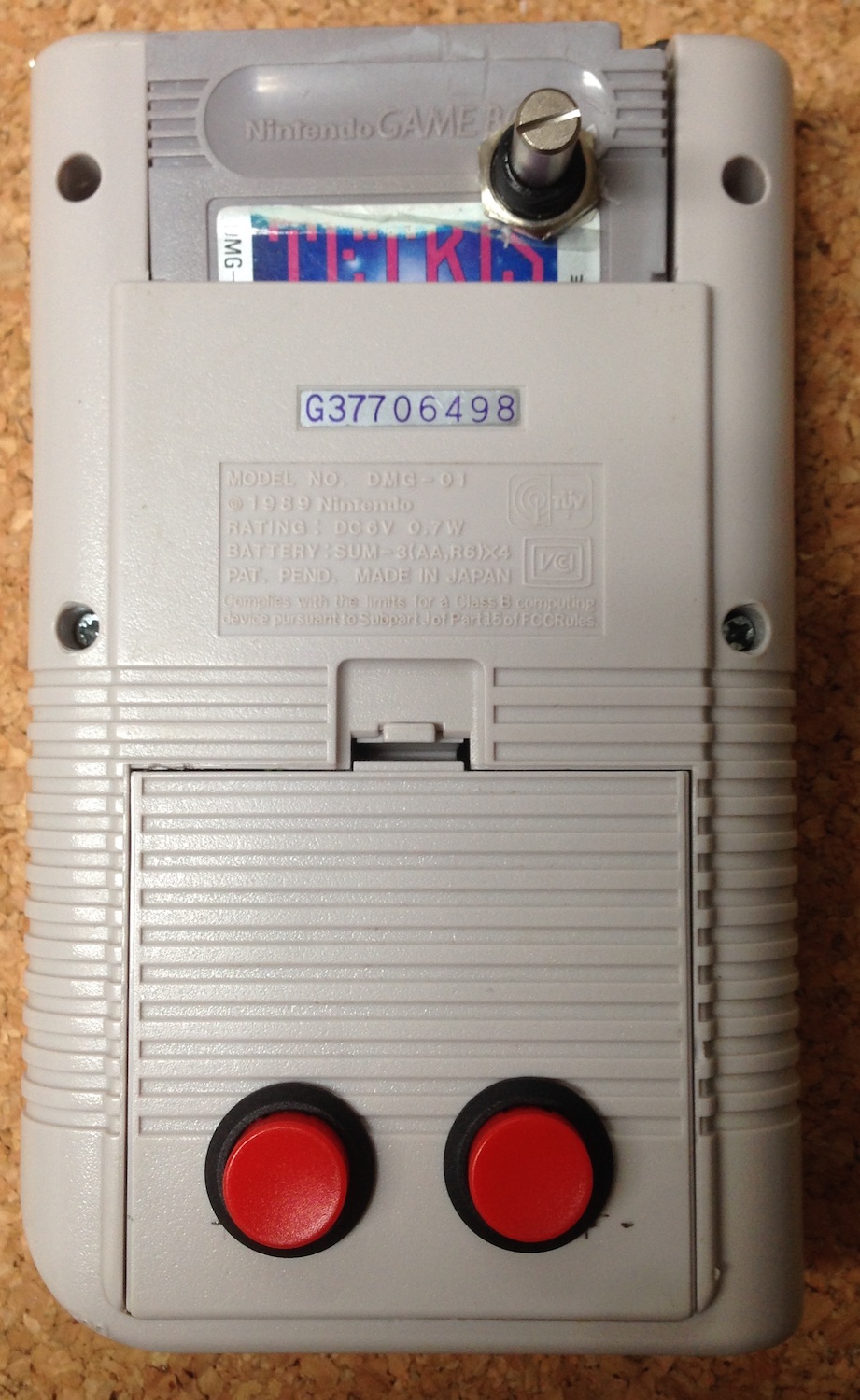
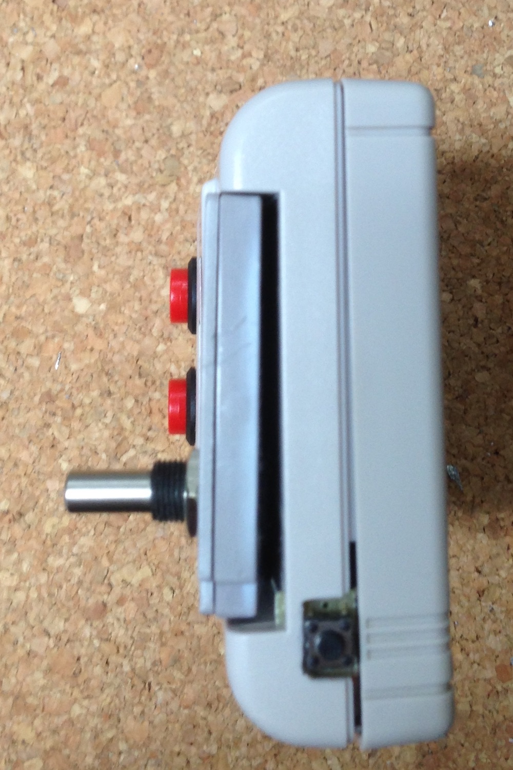
Take the battery cover and drill two holes for the two push buttons. Be careful when using large drills. The cover can slip out of your fingers and cause injury. Prepare a small piece of solderable board for the top switch. You will use it as sort-of power switch to control the emulators. Adjust it to fit where the power switch was.
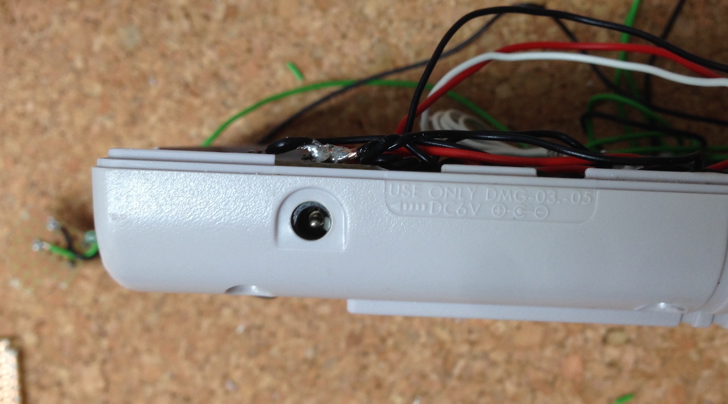
The power connector
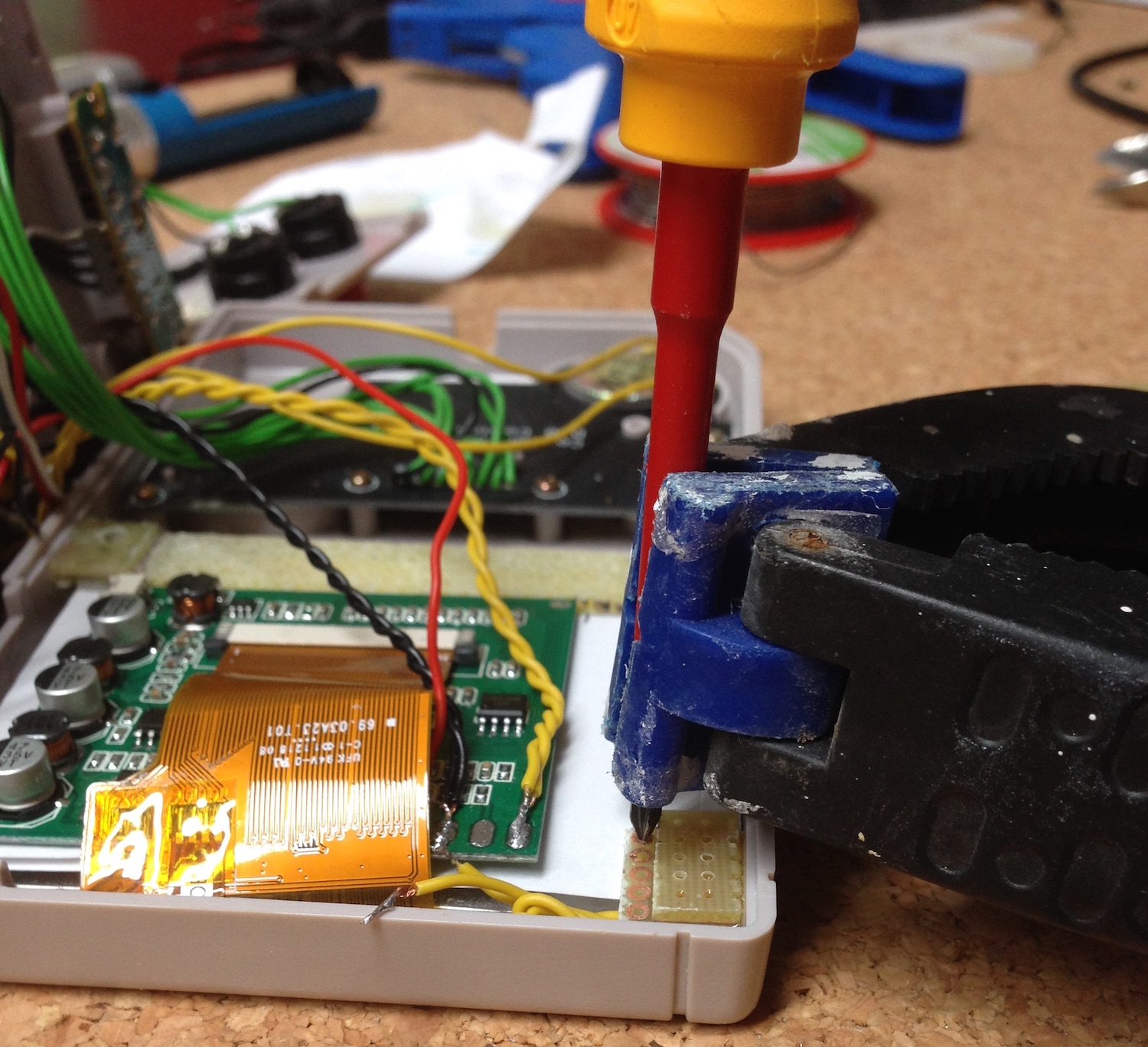
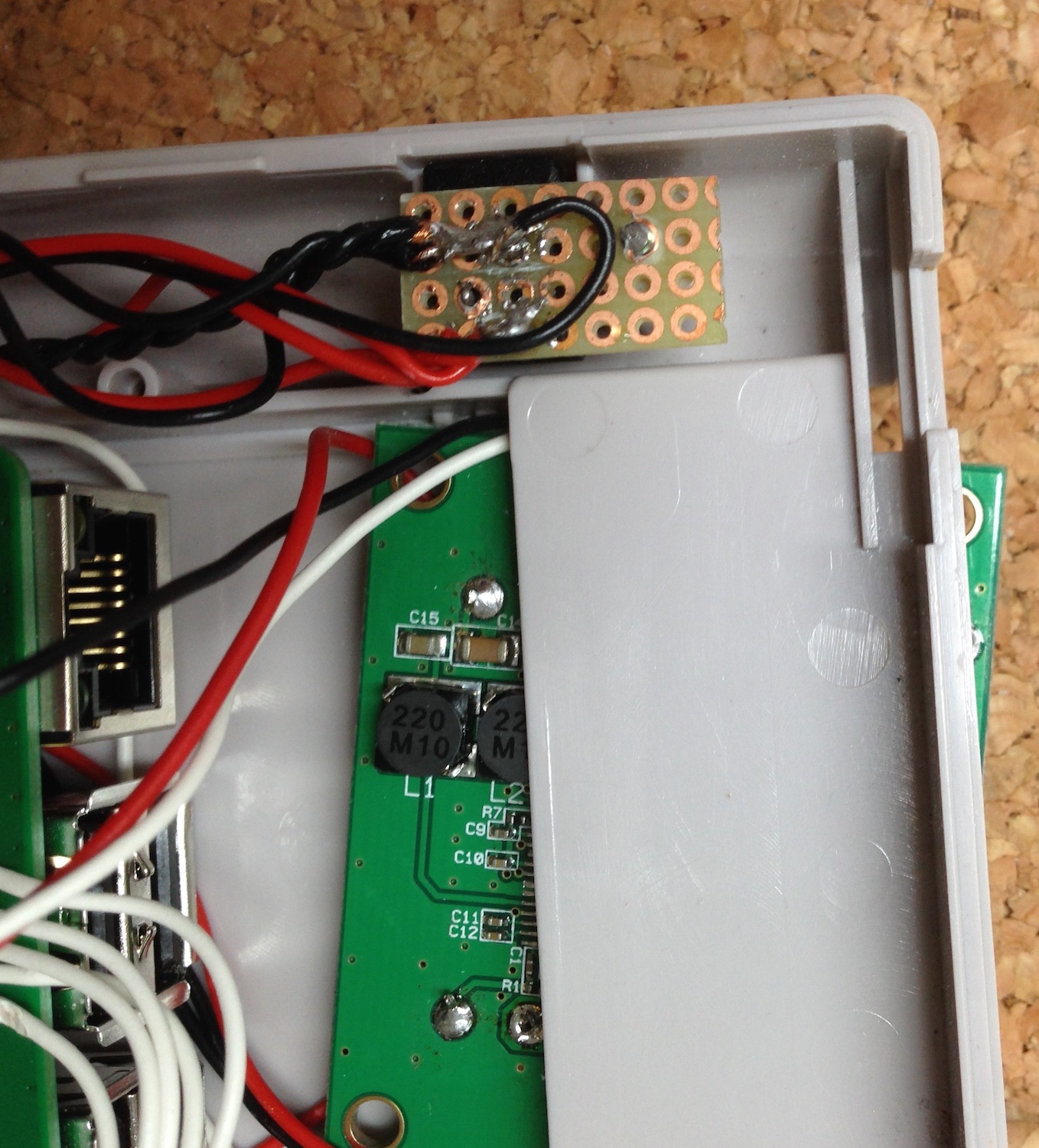
You will need power for your RaspiBoy. I reused the original power connector. I decided to put the positive on the pin and the negative on the shell. I also cut a small part of the soldering board. So I could solder the on the one hand the power connector to the board and on the other hand I had won a base to mount to the case. And one more: You will need a lot of GND (ground). This is also a good base to patch the different cable lanes. Measure and fit the board before cutting it. Then fix the board with a screw and cut off the overhanging part of the screw (for not harming the display).
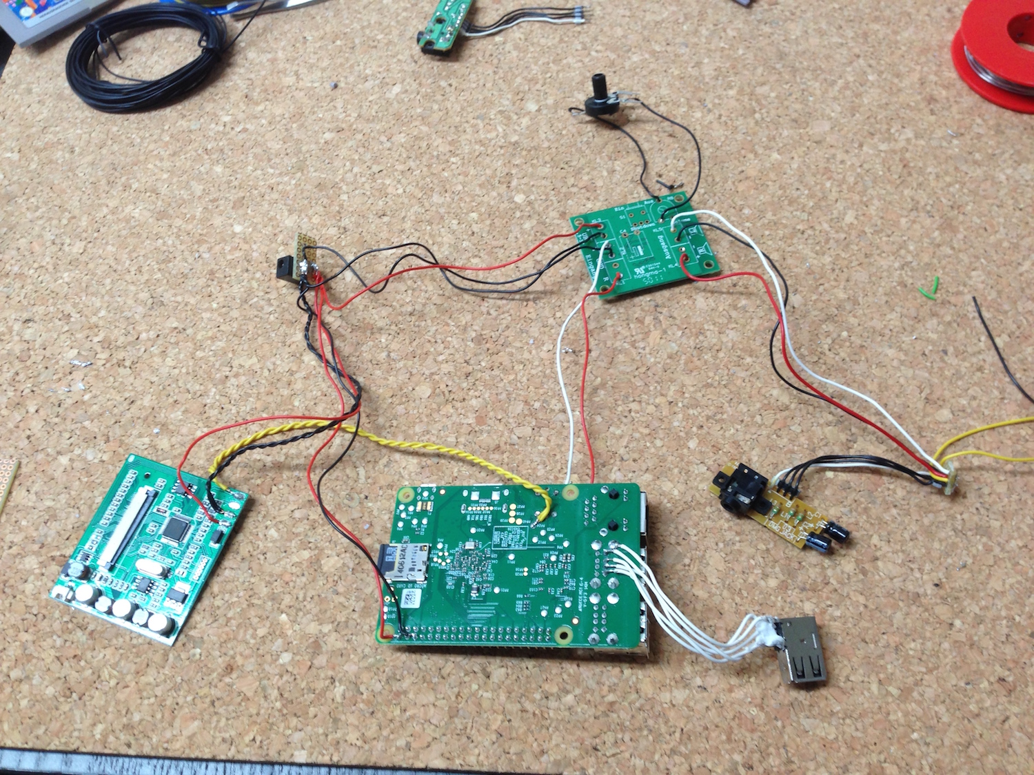
This is a good moment to try to assemble all parts. Make a test whether everything fits and whether you can but the front and back case together. If not, adjust and cut parts as necessary. It's time consuming because you have to put all parts in place, check, identify what's preventing assembly, disassemble, cut, rinse & repeat. See Assembly on how the parts fit together best.
Soldering
Power and GND
Solder 3 wires (ensure they are long enough but not too long, else you will mess at assembly because your wires are too short) to the positive port and 3 wires to the negative.
You need to supply powert to the
- Raspberry Pi
- Display
- Audio Amplifier
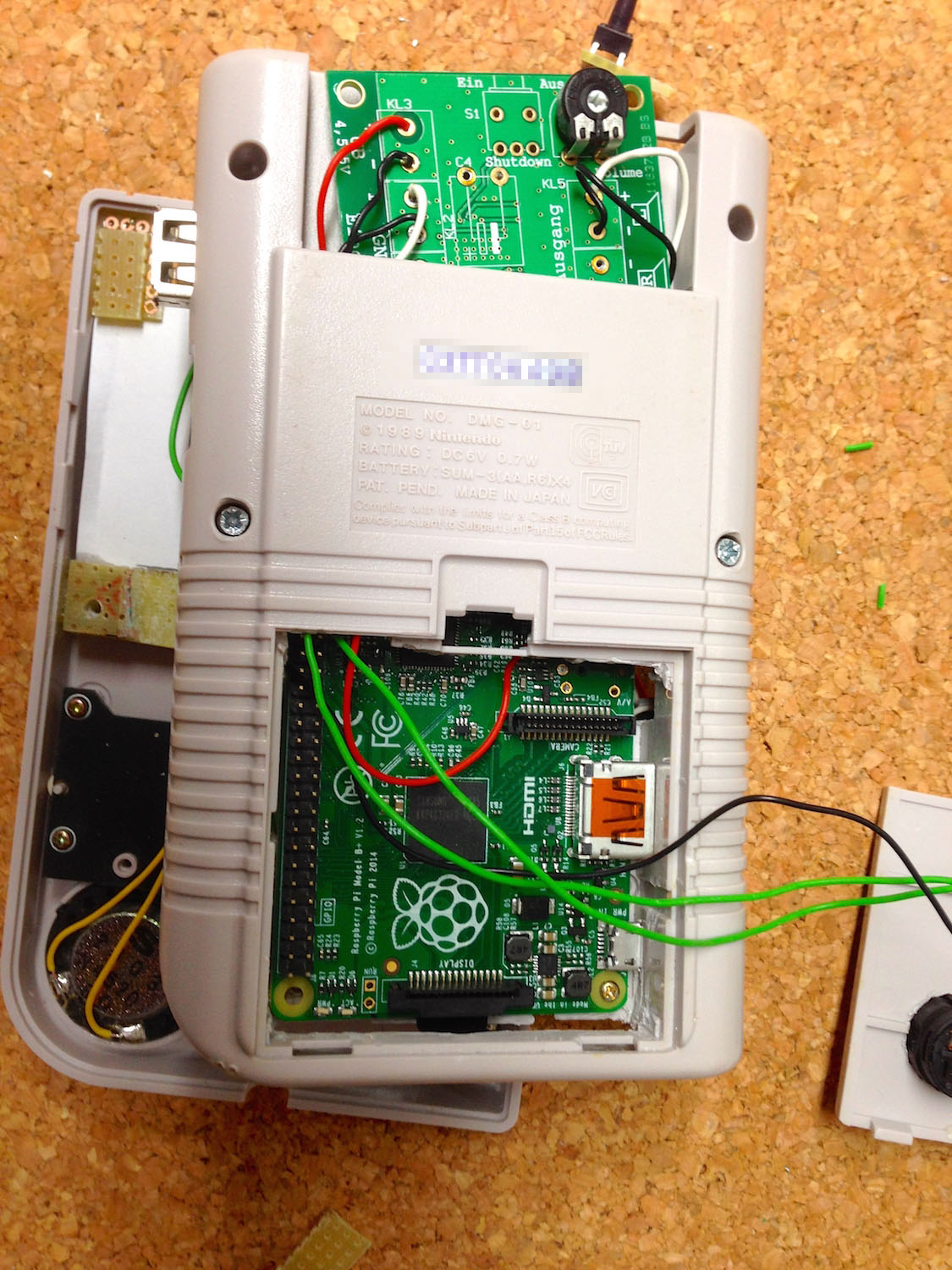
Raspberry Pi
Remove the audio port. Connect wires to the left, right and FBAS/Composite connector. GND is handled by the overall GND port at the power connector. Connect the positive power wire to any 5V pin of the IO pinstripe and the GND to any of the GND pins. I was thinking a lot about soldering vs. a connector. The connector adds some millimeters of height, therefore I decided to connect all wires directly to the pins from the bottom side. Attach wires to the USB port and connect the other sides to a free USB port on the Raspberry (as well on the bottom side).
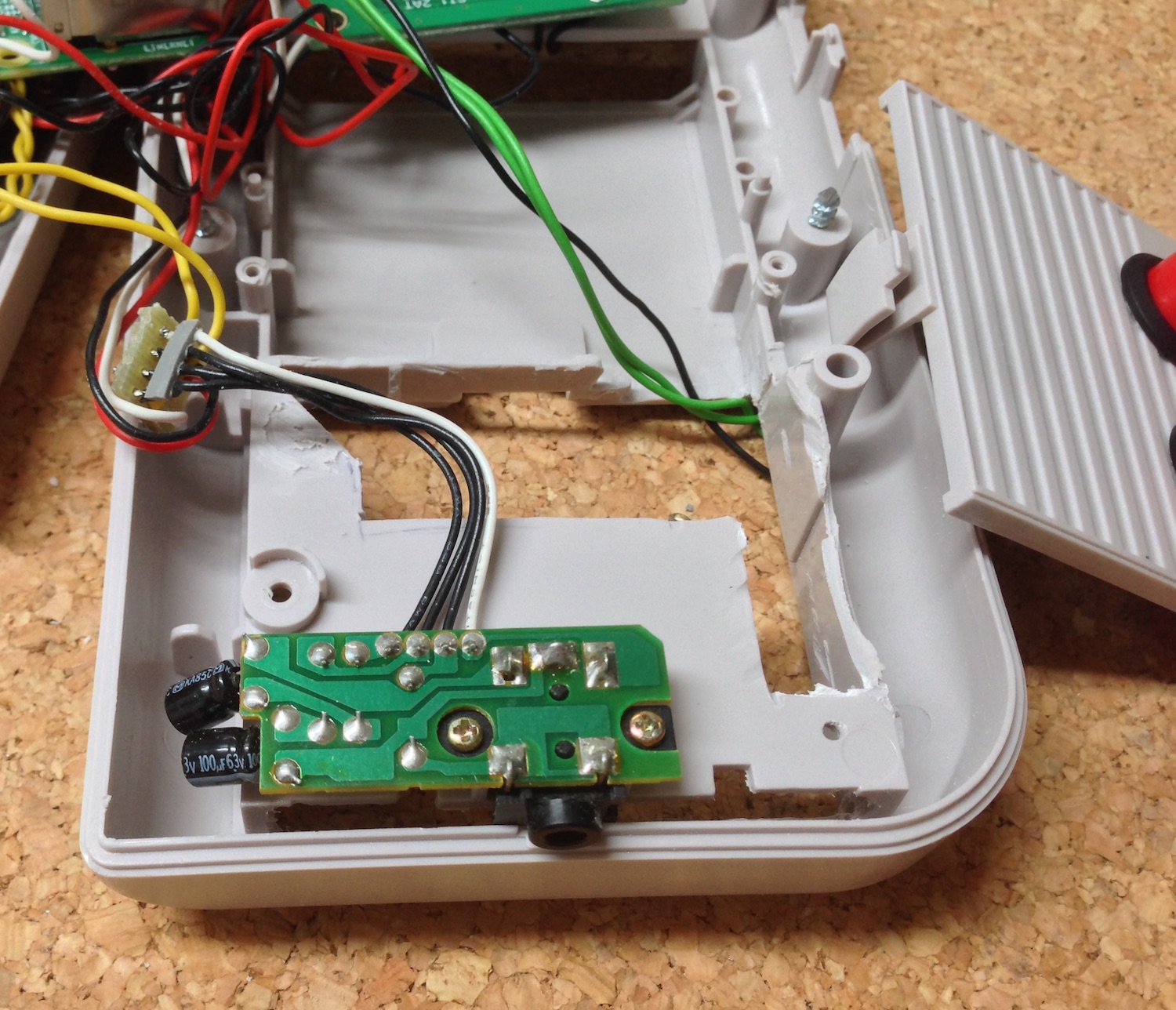
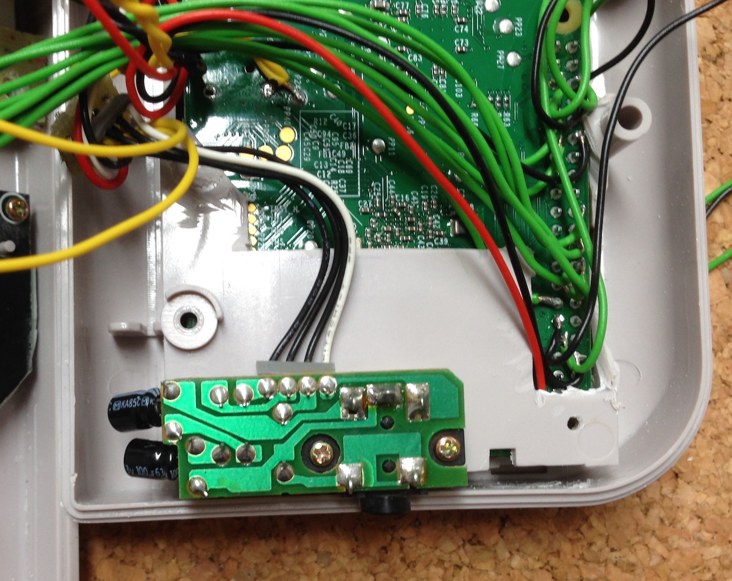
The audio board
The audio board of the Gameboy has four wires. Left, right GND and bridged GND. The bridged GND is connected to the GND if no headphone jack is inserted. As soon as you insert a headphone jack into the audio connector the bridged GND connection will be interrupted and the speaker is muted. That's perfect to achieve the same behavior as the original Gameboy. Connect the output of the amplifier to the according left, right and GND pins of the audio board. Then you have to connect left (or right) and GND with the speaker. I did this using an intermediate soldering board. This gives some stability and avoids false contacts due to not insulated wires. Then attach the wires from the Raspberry (left and right) to the input ports of the amplifier. Next is power. Grab a positive and a GND wire and solder both to the amplifiers' power in, connect the GND also to the audio in GND. This is because GND is GND, the Raspberry audio GND is the same as the power GND.
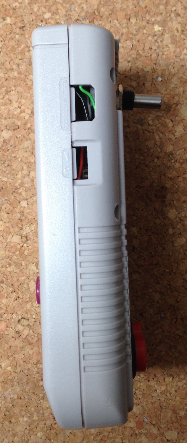
I added an external volume control to change audio volume manually. It was somehow important to me. You can change the volume also using emulationstation by the software mixer.
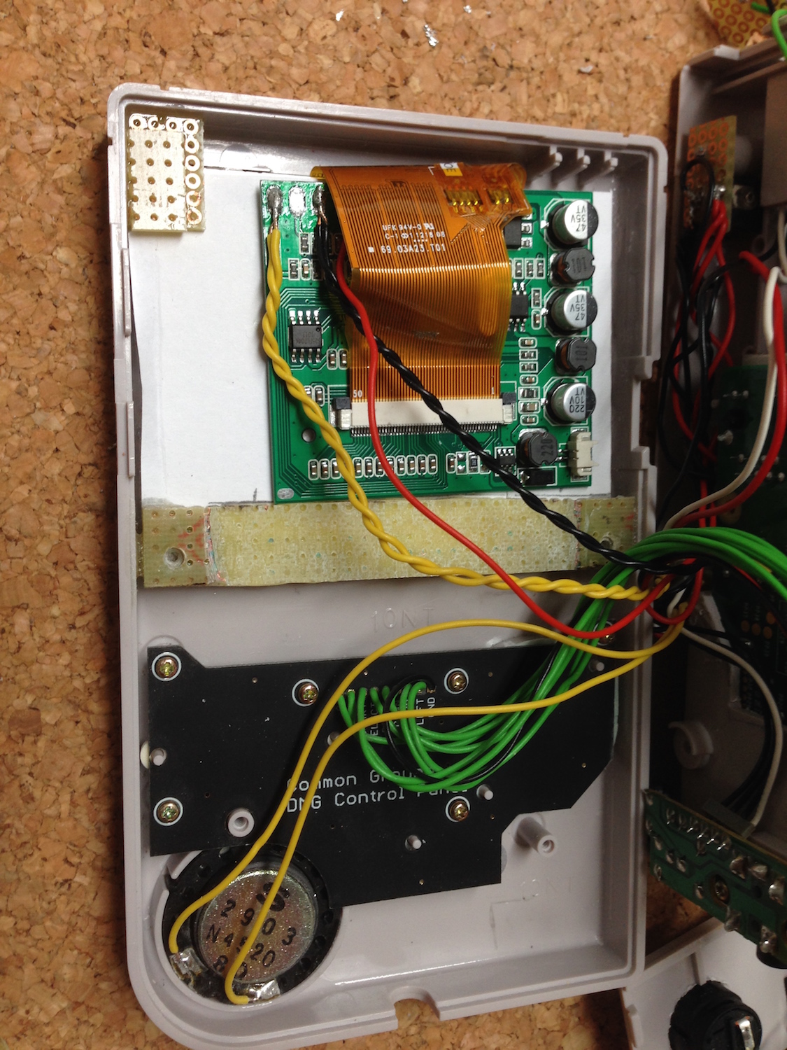
Display
Solder both power wires to the connectors and the FBAS/Composite signal from the Raspberry to Analog In 1. The GND thing is the same like with the Audio. Nothing more to solder here.
Buttons
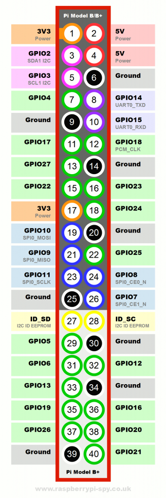
Cut enough wires to connect every button of the common ground PCB (A/B/Start/Select/Up/Down/Left/Right/GND) with the Raspberry. Connect these to with the common ground and the GPIO pins. I used for my wiring only single function declared GPIO pins. Some pins can have multiple functions (such as I2C). I omitted these.
| Pin | GPIO | Button | Mapped to |
|---|---|---|---|
| 7 | 4 | Top Button | Escape |
| 11 | 17 | A | Right Control |
| 13 | 27 | B | Right Alt |
| 15 | 22 | Start | Enter |
| 16 | 23 | Select | x |
| 18 | 24 | Right | Cursor Right |
| 22 | 25 | Down | Cursor Down |
| 29 | 5 | Up | Cursor Up |
| 31 | 6 | Left | Cursor Left |
| 36 | 16 | LB | Page Down |
| 35 | 19 | RB | Page Up |
Soldering to the pins from the bottom side is a bit tricky. You have to have very short uninsulated wire parts and you need to take care not connecting accidentally two pins. So watch out. I connected 2 additional buttons which are used for PgUp/PgDown or X/Y button.
Insert the buttons into the battery cover first, then attach the wires to the buttons and then put the wires though the battery enclosure hole! Else your wires will stay outside the case.
So put the wires through the case and then solder them to the Raspberry. One additional button is for exiting the emulator (ESC-Button). Once you are in a emulator you've got to quit it somehow. You don't want to shut down the whole Raspberry when exiting an emulator. Solder the third button to the tiny solderable board which fits in the power switch slot and connect all buttons to GPIO pins and GND.
Lessons learned: Play around with the device a bit as long as it is not inside the case. I learned from it what else I needed.
USB port
A Gameboy having USB is freaky. I added an USB port in the first approach but removed it later on, because I used
Software setup
All config files so far are available at https://gist.github.com/mp911de/968610d1ff9ce7db5c18
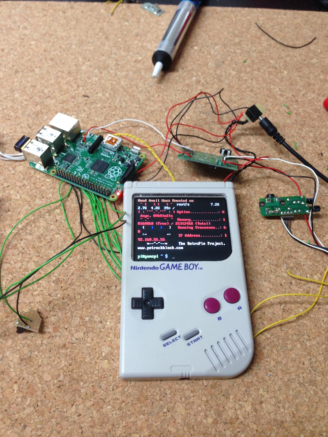
We've gone that far now, so we can use the individual components together. I grabbed the RetroPie image and copied it on the SD card. Connect the display to the controller board, plug in network (Ethernet or WiFi, which requires additional setup ) and start your Raspberry. You will need to adjust the image rotation and perhaps overscan values. Fiddle around with it. After a successful start you'll see the EmulationStation prompting you for setup. Quit it using Alt-F4. Install git, make, gcc, build-essentials, ncurses-dev and expat-dev packages (package names vary between distributions). You'll need them for compiling Adafruit-Retrogame.
Retrogame is a GPIO-to-Keyboard driver. It maps the GPIO buttons to keyboard strokes.
Edit retrogame.c by adding/specifying GPIO port to keystroke. Map one button to KEY_ESC so you can quit a running emulator. Build it and add it to /etc/rc.local and /etc/udev/rules.d/10-retrogame.rules
sudo nano /etc/rc.local
Once the nano text editor loads, add this line into the file right before exit 0:
/home/pi/Adafruit-Retrogame/retrogame &
Then
sudo nano /etc/udev/rules.d/10-retrogame.rules
Once the nano text editor loads, copy this single line into the file:
SUBSYSTEM=="input", ATTRS{name}=="retrogame", ENV{ID_INPUT_KEYBOARD}="1
Run sudo retrogame & to test wether everything is working.
Copy some ROMs into the rom folder (either via Samba share or SFTP in ~/RetroPie/rom/...) and remove any ~/.emulationstation/es_input.cfg to reconfigure your inputs. Restart then.
sudo reboot
Now configure your input controls and give any emulator a try. Everything ok? If not, adjust your controls as needed. Do some test runs before you start assembling.
Assembly
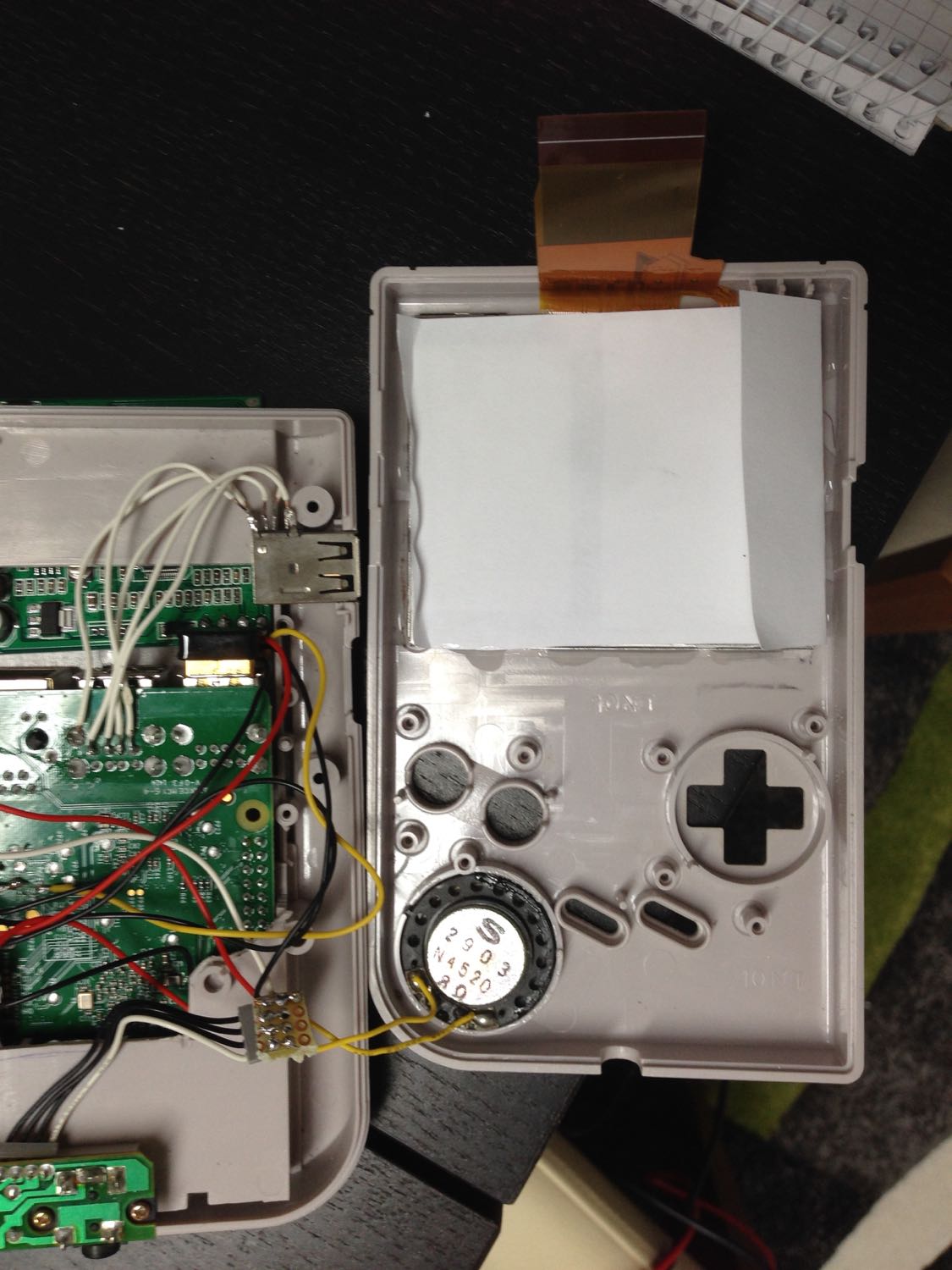
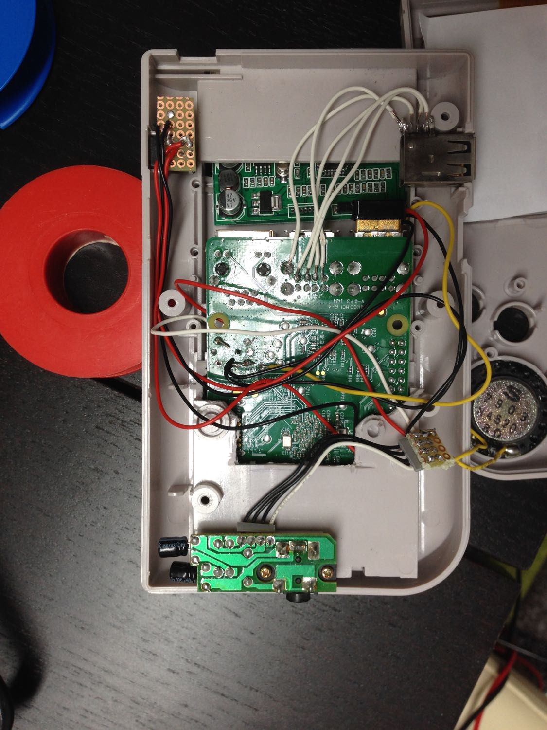
Now it's time to assemble all parts into the case. Be careful to not rip off any wires. Have all case parts separate. Put the Raspberry into the battery enclosing facing the SD card to the bottom of the rear case. The Raspberry fits perfectly to the battery enclosing because the widths are near equal. Put the speaker in place, insert the buttons and pads, lay the common ground PCB over it and tighten it using the Gameboy screws. Mount the audio connector to it's previous position. Put the power connector in place and use a short screw to mount it. Play a bit with the amplifier board and look for a place it fits best. Mine was placed in the game cartridge slot at first. I moved it inside after some case works. Put the USB port into the multiplayer connector slot. It fits there pretty well. Now connect the display, place the display controller right behind the display and put both pieces of the cover together. Do it carefully and do not break anything. Connect the case parts using screws. Do it carefully not breaking the screen due to screws.
Lessons learned: It did not fit in the first try. I had to remove more plastic from the battery enclosure to have more space for the GPIO pins. I drilled small holes to fix the Raspberry within the battery enclosing and I mounted an additional attachment to screen the front and rear cover together in the upper section. I moved the audio amplifier to the inside after having more room because the Raspberry had a better fitting.
Done.
Results
First shot
Final

Special notes on emulators
You will have to do some more config for particular emulators. It took me nearly two days to find relevant configs and the best solution for me. I published my config files at https://gist.github.com/mp911de/968610d1ff9ce7db5c18
Motivation
I stumbled upon http://superpiboy.wordpress.com a time ago. I was fascinated and felt again my childhood. So I started my own project.
There are some other guys having similar projects:
- Raspberry Pi Gameboy Pocket Documentation
- The GamePi Gameboy Case Mod
- Game Boy PC
- PiBoy Advance
- RasppiBoy
- Projekt Raspberry Pi Gameboy
Now my finger hurt from playing too long with a toy sized for much smaller hands.